|
|
|
Last Changed 2/11/2007
|
The AC Circuit in Red Rover's cab are for
powering the refrigerator, microwave, and other conveniences.
|
click on images to enlarge |
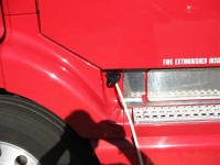 |
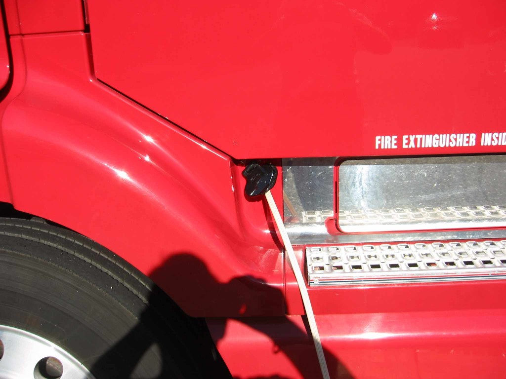
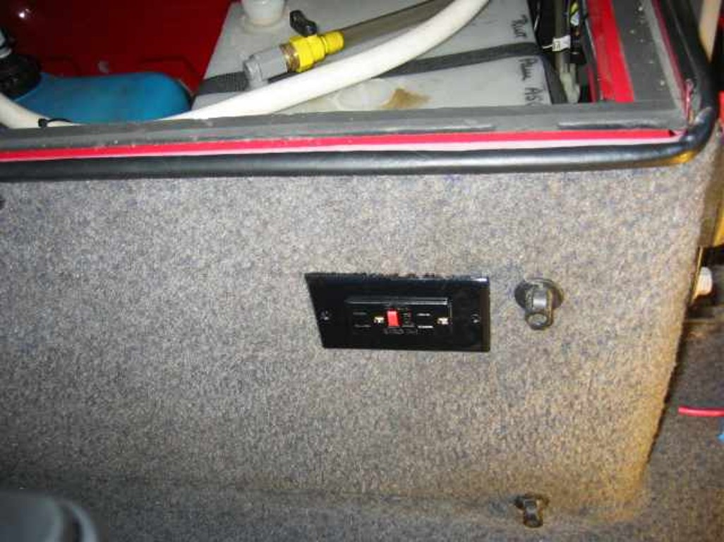
The AC Input jack came with the cab electrification kit described below. |
click on images to enlarge |
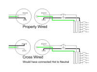 |
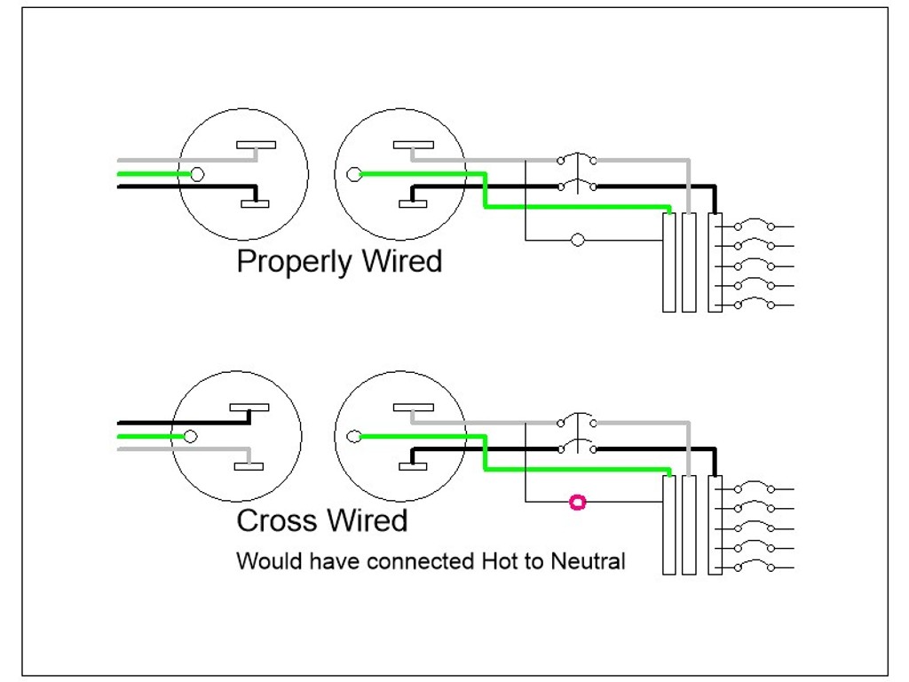
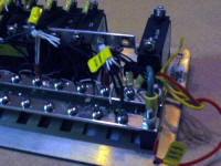
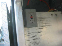
A practice from the boating industry is to use a dual pole breaker
for the AC input. Normally you would consider that just a single
pole breaker on the Hot lead would be enough.
However there is always a chance that the power receptacle you are
plugging into is cross wired. This would mean the shore power Hot
lead would be connected to the Neutral bus in the truck. In a boat,
this would probably cause a smoking condition as the Neutral in a
boat is usually in contact with the water in one way or another and
thus a short circuit is made.
In the truck, the problem could be far worse. The cross wired short
could occur when you become the path between the truck Neutral and
the ground.
The light will be lit if the receptacle is cross wired. |
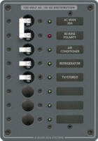 |
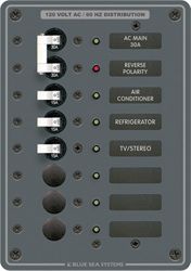
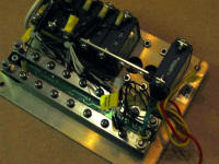
This dual pole breaker is mounted on a Distribution Panel that we
purchased from a marine supply store. Most of the wiring components
used are marine grade, mainly because the marine industry uses the
items we wanted to use.
The Distribution Panel has bus bars for AC circuit breakers and
connections. There are a Ground, Neutral, and a Hot Bus Bar.
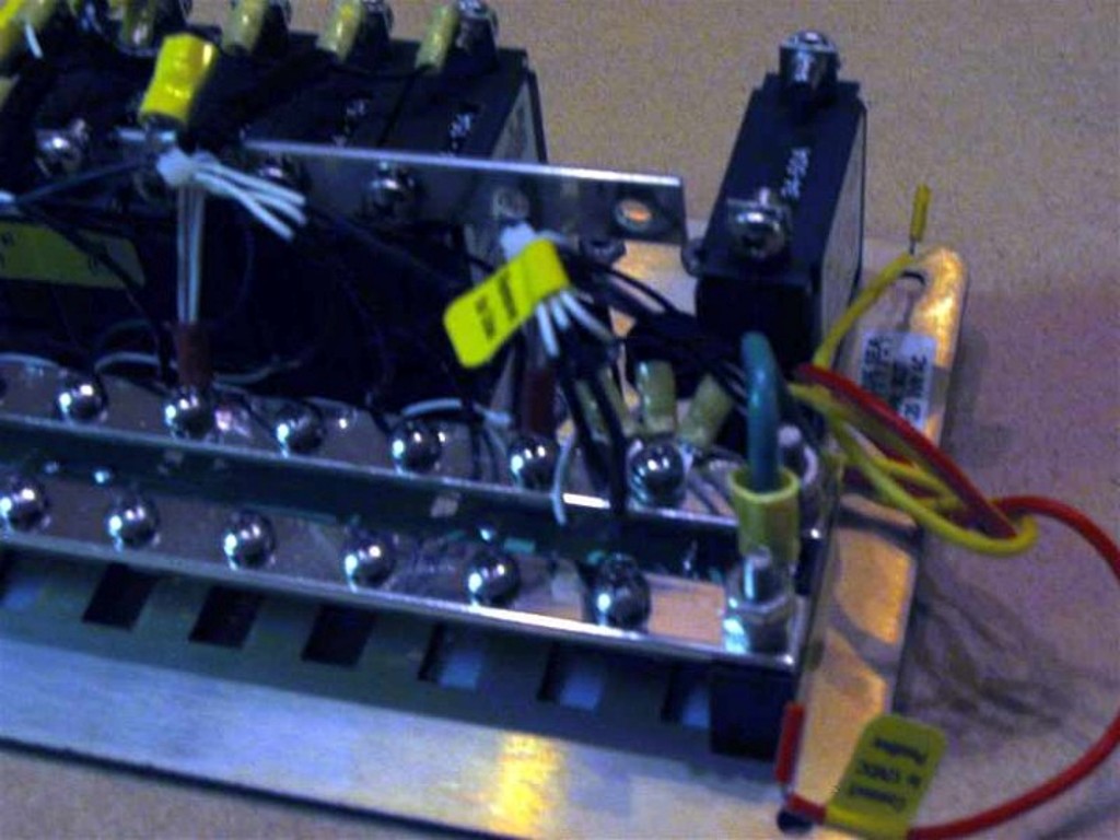
Normally the hot lead of the Input Breaker is attached to the Hot
Bus Bar to feed the other breakers. We disconnected that jumper.
The Hot Input Breakers is attached to the Inverter/Charger Hot AC
Input. The Neutral Input Breaker is attached to the Neutral Bus
Bar. The Neutral AC Input and Output of the Inverter/Charger are
also attached to the Neutral Bus Bar. The Inverter/Charger Hot AC
Output is attached to the Hot Bus Bar. The Inverter/Charger has an
internal breaker to handle the Hot Bus Bar.
All Ground connections are made to the Ground Bus Bar. The Ground
Bus bar has a direct connection to Frame Ground.
We used five of the circuit breaker locations for the AC circuits in
the cab.
We shortened the Hot Bus Bar so we could mount a DC circuit breaker
in the bottom breaker location. Actually, marine circuit breakers
are AC/DC, current being current. The circuits they are connected
to determine whether they are AC or DC |
 |
click on images to enlarge |
 |
 |
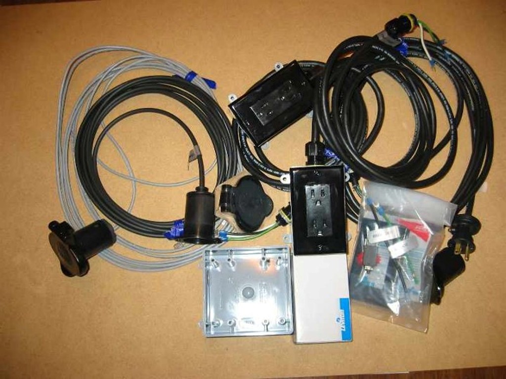
We found some sleeper cab wiring kits on eBay. We used parts from the kits plus some new wire to place the outlets within the cab. |
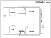 |
These are the locations of the 110 volt outlets running off the inverter/charger and shore power. |
click on images to enlarge |
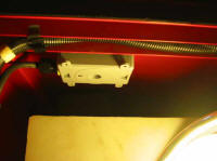 |
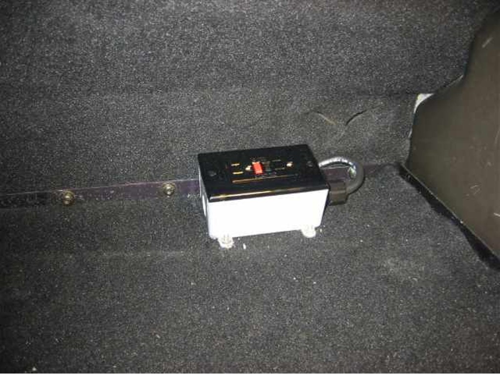
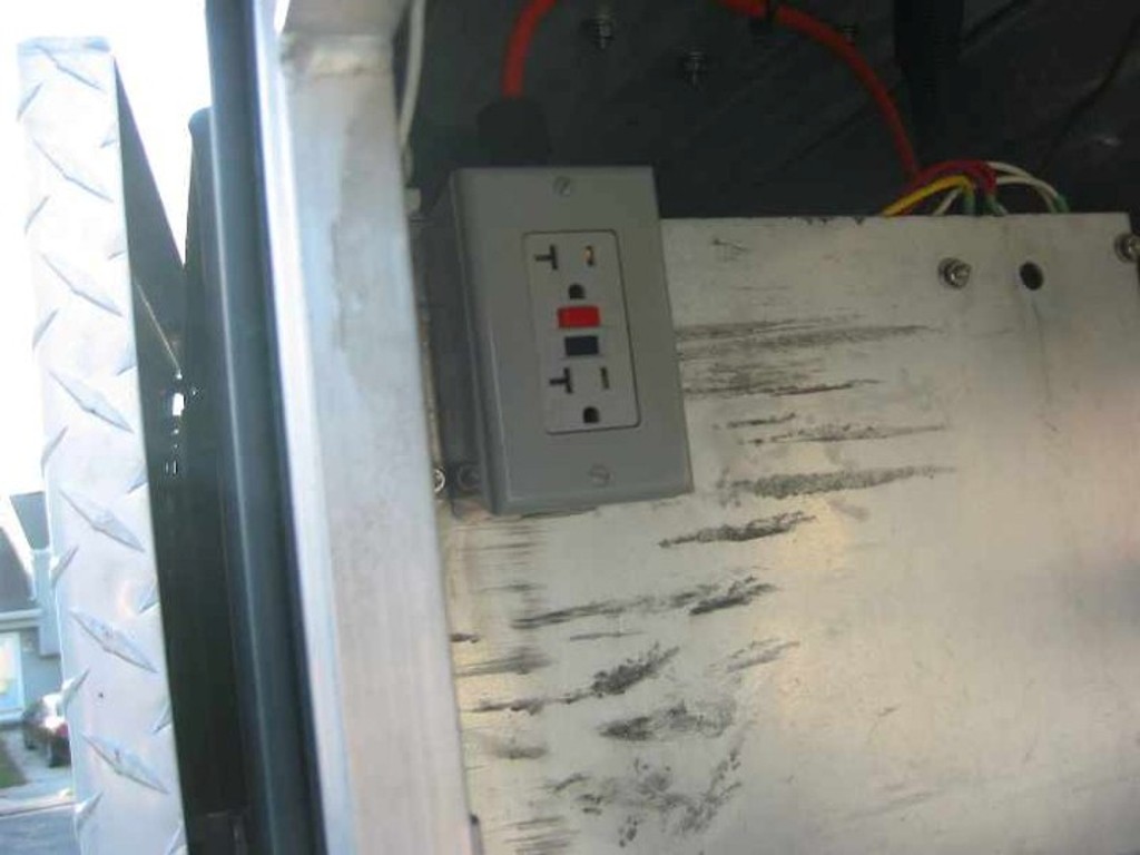
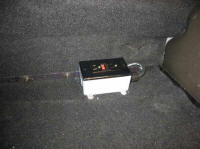
Outlet mounted in left baggage compartment. The wall of the
compartment was pre-punched with a cutout for the outlet. |
 |
click on images to enlarge |
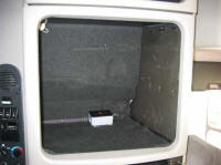 |
This is the compartment over the sink. It is used for the microwave/toaster oven. There was a standard DC outlet and we added an AC outlet. |
 |
click on images to enlarge |
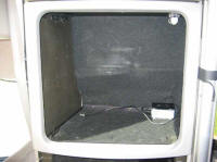 |
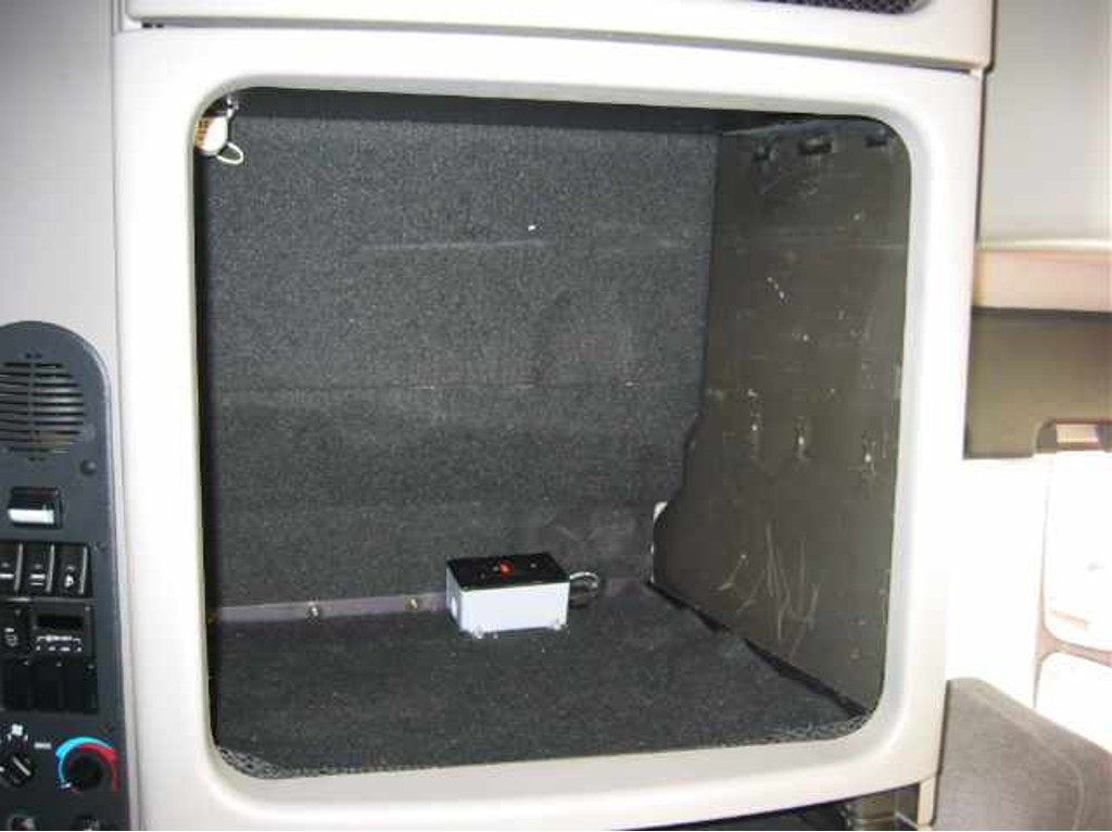
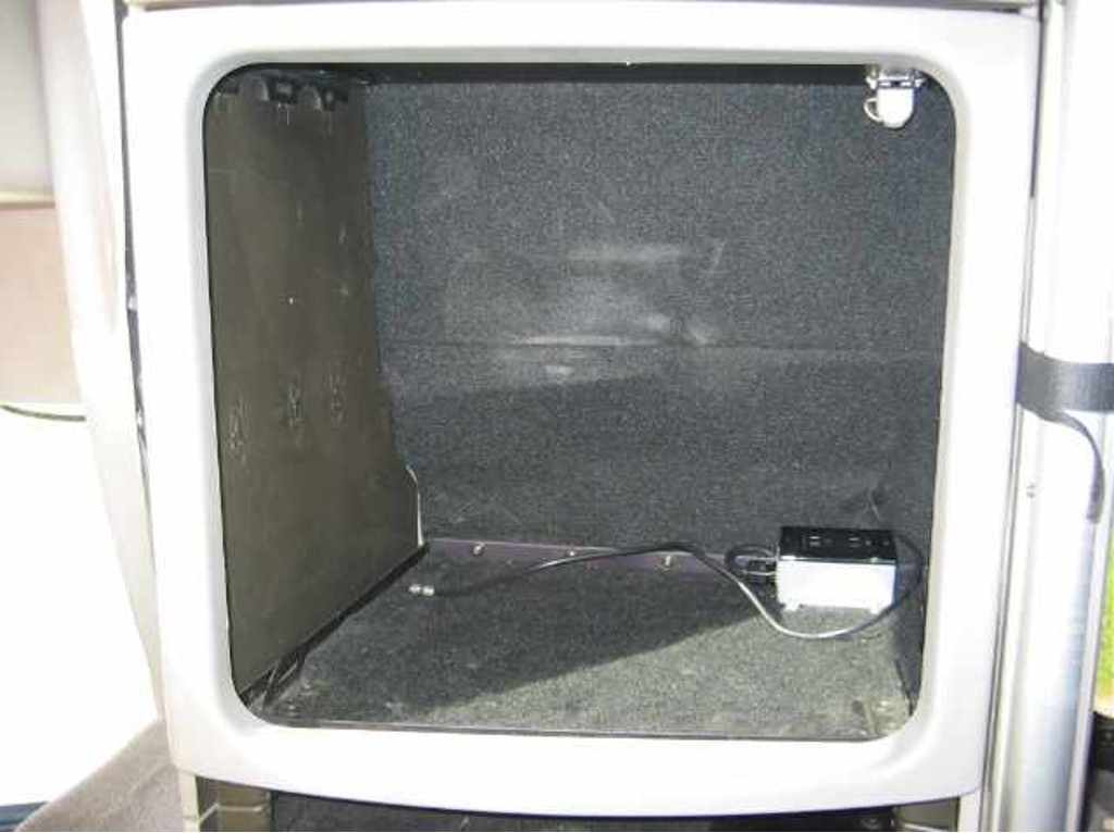
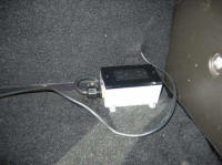
This is the TV compartment. There is a DC outlet standard and we added an AC outlet. Note the antenna cable to the antenna built
into the cab roof. |
 |
click on images to enlarge |
 |
An AC outlet was installed in the Headache Rack Cabinet to facilitate working with power tools. |
click on images to enlarge |