 |
 |
 |
Last Changed 11/4/2014
|
Even though we have a longer than normal power cord for Tige, we
find we often have to use an extension cable as more and more RV
parks that we use are geared for motorhomes rather than trailer.
RV trailers tend to have their power inlet at the rear street side
corner of the trailer. Motorhomes tend to have their power
inlet located in the middle of the street side of the motorhome.
We wound up with a spare 50 amp power inlet from an incident last
year. We decided to add a second power inlet near the front
street side of Tige.
The power inlet is one of the expensive parts of this project.
The second expensive part was the wire (#6-3 with ground) was $3.26 a
foot and we used 18'. Finally, the Automatic Transfer Switch was
the third expensive item (about $100).
Automatic Transfer Switch (ATS)
When you have two power inlets, you might think you just combine the
wire from each inlet to the electrical system of the RV. This is not
a smart thing to do for two reasons. First, the places the wires
would be attached probably can't hold two #6 wires. More importantly,
connecting the two power inlet in parallel can be extremely dangerous.
When The power cord is in one inlet, the other inlet's blades would be live with
120/240 volts. Though not probable, the possibility is there for an
inquisitive child to open that mysterious cap on the unused power inlet.
Therefore fore safety sake, we used a ATS. An ATS has two relays inside
that connect only one of the two inputs to the output. Thus the unused
leg is isolated from electricity. The automatic switching
happens by monitoring the input legs of the ATS. When there is
voltage on the secondary input, the that relay is energized and the
primary relay is opened. For example, when we start the
generator, when the generator voltage is present, then the power
cord is disconnected. |
 |
This is a schematic of what our input power would be like. We
already had a ATS to switch between the power cord and the
generator. We will be adding an ATS on the power cord input of
the existing ATS to switch between the two power inlets. |
 |
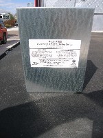
Here is the ATS that we bought for this project. It is a Progressive Dynamics 50 amp Transfer
Switch Model PD52. We bought ours on eBay. |
click on pictures to enlarge |
 |
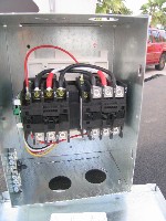
You can see the two relays that with connect only one of the inputs to the output. In this ATS, the right relay is connected to
the existing power inlet. The left relay is connected to the new
power inlet.
A small circuit board does the sensing of voltages on the inputs to
determine which relay should be energized. |
The Installation
|
 |
This is the existing ATS that switches between the power cord and the generator. |
click on pictures to enlarge |
 |
The existing ATS also has two relays. There are some extra
wires in this ATS as there is a delay when the generator comes on
line. This allows the generator to stabilize before the load
is applied. |
 |
We were constrained by the lengths of the existing wiring. In
a perfect world, the current ATS would have been relocated.
Unfortunately, the ability to stretch wire is limited. So we
had to deal with the current ATS were is was and added the new ATS
where we could. Also, #6-3 Romex is fairly stiff and does not
make sharp bends.
We moved the current power inlet wire from the top of the existing
ATS and connected to the new ATS. Then a cable from the output
of the new ATS was fed into the correct ATS power cord input. |
click on pictures to enlarge |
 |
This is the area just behind the cargo door on the street side.
There is a panel I removed for access. We had mounted the new
power inlet when we have the trailer repaired so the new inlet would
be painted to match the trailer. |
 |
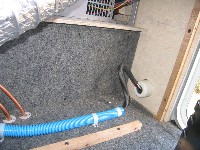
We ran the #6-3/ground Romex through non-metallic conduit for protection of the Romex.
We had to have a bend in the wire so it could be attached to the
power inlet. The power inlet core is pulled out to attach the
wires. |
click on pictures to enlarge |
 |
This is the new power input located just behind the street side cargo door.
Now when the park power post is near the front of the trailer, this
is the inlet we will use. |
click on pictures to enlarge |
This is a tiring job as the #6-3 Romex takes a lot of manhandling to
get it in place. Then getting the #6 wires into the relay connectors takes
a fair amount of hand force. Other than that, this is not a complicated job.
|
Update |
| We had a small problem where the ATS between the two power inlets didn't always pick
a couple of times. We contacted the manufacturer and found we had missed one line in the
installation manual about mounting the ATS so the relays were horizontal (the pivot
shafts of the relays being horizontal). We had mounted the new ATS
in the vertical position. We did not relish the task of
reinstalling the ATS in the horizontal position |
 |
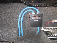
Since this was the second time, the wiring came out neater than the
first installation.
Still difficult to work with the stiff #6 wires. |
click on pictures to enlarge |
 |
We removed the blue non-metallic conduit from one of the power cables to make
tighter turns.
The cable is protected by the new ATS. |
click on pictures to enlarge |

